Showing posts with label Cisco. Show all posts

Friday, January 6, 2012

How to create a frame relay switch

Here I am going to demonstrate how to configure cisco router as a frame relay switch. The configuration is very simple. So check the figure below carefully and understand the configuration.
frame relay switch
Connect the routers as in the figure.Here I am creating two PVCs – first one between R1 & R2, and second one between  R1 & R3

Wednesday, January 4, 2012

Routing vs. Routed Protocols

Before talking about the routing and routed protocols, look at the screen shot from Google map. How many way to reach from point A to Point B?
image
Okay, you don’t need to count. There are plenty of ways. isn’t it? how will you select the right path from point A to Point B? We may consider different aspects for this - fast way, way with low transportation charge, etc.

Wednesday, December 28, 2011

Difference between Protocol number and Port number

Protocol number is the value contained in the “protocol” field of an IPv4 header. It is used to identify the protocol. This is an 8 bit filed. In IPv6 this field is called “Next header” field. Some of the protocol numbers of commonly used routing protocols are given below:
Protocol Protocol Number
EIGRP 88
OSPF 89

Monday, December 26, 2011

Different types of communication systems

Simplexsimplex half duplex and full duplex communicaitons

In this type of communication, first device send data and second device receive it. Second device never send  any information to first device. Broadcast systems like FM radio work in this way.

Half Duplex

In this type of communication, when first device send data, second device receives it and when second devices send data, first device receives it. But both devices can’t send or receive data at the same time. This type of communication is using in "walkie-talkie".

Full Duplex

In this type of communication, first and second device can send and receive data simultaneously. Phones and mobile phones are using this type of communication.

Note: In Ethernet communication we can set both end half or full duplex depending up on the requirements. That is Ethernet can work on both mode.

Sunday, December 25, 2011

Basic Switch Configuration

Before begin configuration we need to see the current status of switch. This can be don using verity of ‘show’ commands. Some of them are given below

  • SW1#Show int status  ;shows description of ports, status, VLAN in which port is connected to, duplex, speed of each interface  etc.
  • SW1#show int fa0/1 ;This command shows interface specific details like Transmission rate, error state, etc.
  • SW1#show run int fa0/1 ;This command shows the commands entered under the interface fa0/1, in the running configuration
  • SW1#show power inline : This command shows the power settings of each port. Used for VoIP devices. If you don’t know about inline power, please check here

Now, lets set the interface attributesCisco switch port

Setting interface attributes

The syntax is as follows:

interface type mod/port

speed {10 | 100 | 1000 | auto}  ;This command tells transmission speed. It can be set depending on Speed of Interface. Normally Switch detects the speed correctly. Default configuration is “auto” ie. automatically detect the speed

duplex {half | full | auto} ;set the duplex of interface. Default is auto. But it is better to hardcode by command on both side.  If you set duplex to auto then make it on both side. Also, if you set duplex make sure that it is typed on both side, otherwise mismatch will happen. If you don’t know about duplex, please check here

mdix auto ;This is the default setting. . This permit switch to automatically discover if a crossover connection is needed. we can change the setting by “no mdix auto” command

media-type {sfp | rj45} ;detects automatically. sfp used for fiber optic ports

Sample configuration is given below:

SW1(config)#interface fa0/1

SW1(config-if)#speed 100

SW1(config-if)#duplex full

SW1(config-if)#no shut (to enable the interface)

Ok. That’s enough. But the problem is, we have to type it on all interface. Hmm… It has an easy way – use the ‘range’ command

SW1(config)#int range fa 0/1 - 4 , fa0/15 ;comma is surrounded by space. This will select the specified range of interfaces i.e. from fa0/1 to fa0/4 and fa0/15 at the same time. Now we can set any attributes to that interface.

SW1(config-if-range)#shut

Setting inline power

SW(config-if)#power inline {auto|never} :to automatically discover power need by port or disable power

SW(config-if)#power inline {consumption mw | static max mw} : to give power specifically

Saturday, December 24, 2011

Inline Power / Power over Ethernet (PoE)

Inline Power and  PoE are used to provide power to IP phones, wireless access points etc. by the catalyst switch trough the same data cable.

In the reality, as you may know, out of 8 channels in the UTP cable, only 4 is used for data transmission. So these methods use the rest to provide power to the devices. PoE-Inliine

Cisco Provides 3 methods to deliver current through the Ethernet cable:

  1. Cisco Inline Power
  2. 802.3af PoE
  3. 802.3at PoE+
Property Inline Power 802.3af 802.3at PoE+
Standard Cisco Proprietary IEEE standard IEEE standard
Maximum power delivery 7W/port 15.4W/port 34.20 W
Cable speed 10/100 only Compatible with gigabit Ethernet Compatible with gigabit Ethernet
Compatibility Incompatible with all non-Cisco devices that accept power over Ethernet Not compatible with Cisco inline power – the power negotiation process is completely different Backward compatible with 802.3af


The devices connecting to the port are divided into different classes depending up on the power consumption:

Class Max Power  
0 15.4 W Default
1 4.0 W  
2 7.0 W  
3 15.4 W  
4 Undefined Future Use


Some advantages of using these methods are:

  • Centralized point of power
  • Centralized point of backup
  • Cheaper cabling

Configuration

Switch#show power inline ;to see the current status of ports

Switch(config-if)#power inline {auto|never|delay}

    • auto: automatically detect power
    • never: to disable power supply through that port
    • delay: wait up to the given delay time before turning off the power of that port if the phone went offline. This is useful when phone is rebooting.

Switch(config-if)#power inline {consumption mw | static max mw} ;to give power specifically

Note: We don’t need to type any command. Cisco switch detect all cisco devices and power needed by the devices automatically using CDP.

Friday, December 23, 2011

VTP

VTP stands for VLAN Trunking Protocol. Unlike the name implies, VTP is used for replication of VLAN information. That means, we just need to create VLANs or edit VLAN information only on one switch. Then VTP will transfer that information through the trunk link to all other switches which make the administration centralized.

VTP works based on the revision number. By default, VTP revision number is 0 on all switches. If we change any VLAN information on a switch, like… adding VLAN, deleting VLAN, renaming VLAN, etc.. the revision number increases. When other switches get the VTP update, it check the VTP revision number contained in the update with its on VTP revision number. If the local revision number is lower than the one it received, it replace the whole VLAN database with the currently received database.

VTP has three modes – Server, Client and Transparent. Depending upon VTP mode in which the switch operates, it gets the features as follows:

  • Server(default)
    • Power to change VLAN information
    • Sends and receives VTP updates
    • Saves VLAN configuration
  • Client
    • Cannot change VLAN information
    • Sends and receives VTP updates
    • Does not save VLAN configuration
  • Transparent
    • Forwards(passes through) VTP updates
    • Does not listen to VTP advertisements i.e.. it does not update its VLAN information using the VTP updates from other switches
    • Power to change local VLAN information
    • Saves VTP configuration (local)

By default cisco switches comes with VTP server mode. Because of there is no VTP Domain name applied to new switches, they act as server for themselves. Also, switches doesn’t participate in VTP until they hear VTP advertisement from another switch.

To see the current VTP status, use the following command

SW1#show vtp statusVTP Modes

Now lets make VTP run on every switch as in the figure.

Set VTP management domain name on all switches

SW1# vtp domain TestDomain

SW2# vtp domain TestDomain

SW3# vtp domain TestDomain

Note: If there is no domain name exist in all switches, then if we configure domain name on SW1, all switches get it automatically.

Set VTP mode of each switch

SW1# vtp mode server

SW2# vtp mdoe transparent

SW3# vtp mode client

Set VTP password (optional)

eg: SW1# vtp password P1ssw0rd

Note: if we want to set the password, set it on all switches

Set VTP version

Default VTP version is 1. if we want to change it to version 2, then do the following command on all switches

eg: SW1# vtp version 2


VTP synchronization issues

If we accidently connect a switch with higher revision number and same domain name to the network, all the switches will replace their database to it’s database. Then network connection may not available to users.

Solution:

Before attaching the switch to the network, reset its revision number to zero. Do one of the following to reset revision number to 0

  • Change VTP mode to transparent, then back to server
  • Change VTP domain to a bogus name, then back

Thursday, December 22, 2011

Private VLAN

Private VLAN is the technique of dividing single VLAN into different sub VLANs. This is generally used in the ADSL networks. Also, we can use it to simplify the IP address assignment because all ports are in the same subnet, although they are logically separated in the data link layer.

Private VLAN contains two components

  1. Primary VLAN, which is the real VLAN
  2. Secondary VLANs, which are the sub VLANs

Secondary VLANs can be one of these:

    • Isolated
      • Ports associated with this VLAN cannot communicate each other
      • Ports associated with this VLAN cannot communicate with any other private VLAN
      • Ports associated with this VLAN can communicate only with Primary VLAN
    • Community
      • Ports associated with this VLAN can communicate each other
      • Ports associated with this VLAN cannot communicate with any other private VLAN
      • Ports associated with this VLAN can communicate only with Primary VLAN

Now lets, Create these VLANs as in the figureprivate vlan

Creating Community VLANs

Sw1(config)# vlan 100

Sw1(config-vlan)#private-vlan community

Sw1(config)# vlan 200

Sw1(config-vlan)#private-vlan community

Creating isolated VLAN

Sw1(config)# vlan 300

Sw1(config-vlan)#private-vlan isolated

Creating primary VLAN and joining it with primary VLAN

Sw1(config)# vlan 500

Sw1(config-vlan)#private-vlan primary

Sw1(config-vlan)#private-vlan association 100,200,300

To proceed to next step, we must understand about different types of ports

There are mainly two types of port in Private VLAN - Promiscuous port and Host port. Host port is further divides into two types - Isolated port and Community port.

  • Promiscuous port : This port can communicate with anything connected to primary or secondary VLANs. Usually, router, firewall etc. are connect to this port
  • Isolated port: This port connect to hosts within the isolated VLAN. It can only communicate with the promiscuous port
  • Community port :  This port connect to hosts within the community VLAN. It can communicate with promiscuous port and other ports in the same community VLAN

Now, lets assign these different types of port to different VLANs we created. Remember, every ports except Promiscuous port are host port. So the VLAN which we assign these ports determines whether it is isolated port or community port.

SW1(config)#int range e0/1 - 2
SW1(config-if-range)#switchport
SW1(config-if-range)#switchport mode private-vlan host
SW1(config-if-range)#switchport private-vlan host-association 500 300

SW1(config)#int range e1/0 - 1
SW1(config-if-range)#switchport
SW1(config-if-range)#switchport private-vlan host-association 500 100

SW1(config)#int range e1/2 - 3
SW1(config-if-range)#switchport
SW1(config-if-range)#switchport private-vlan host-association 500 200

SW1(config)#int e0/0
SW1(config-if)#switchport
SW1(config-if)#switchport mode private-vlan promiscuous
SW1(config-if)#switchport private-vlan mapping 500 100,200,300

Wednesday, December 21, 2011

Commonly Using Port Numbers

Port TCP UDP Description
20 x   FTP-Data
21 x   FTP (login access)
22 x x SSH
23 x   Telent
25 x   SMTP (Mail, MTA)
49 x   TACACS+
53 x x DNS
69   x TFTP
80 x x HTTP (Web)
110 x x POP3 (email); generally uses TCP)
119 x   NNTP (Usenet News)
123   x NTP
139 x x NetBIOS (Microsoft)
143 x x IMAP
161 x x SNMP (Network Monitor)
179 x   BGP
443 x x HTTPS
465 x   SMTPS (Secure Mail over SSL)
993 x x IMAP (Secure IMAP over SSL)
995 x x POP3S (Secure POP3 over SSL)
1645,1812   x RADIUS Authentication
1646,1813   x RADIUS Accounting

Thursday, December 8, 2011

Configuring ASA to allow ping

Just add ICMP to default inspection class:firewall
ASA(config)#policy-map global_policy
ASA(config-pmap)#class inspection_default
ASA(config-pmap-c)#inspect icmp

Tuesday, November 29, 2011

Monitoring Internet Connection using IP SLA

Our company may have two connection to the internet through 2 ISPs. If we want to use one connection as primary and other as backup, we can use IP SLA to monitor the link. It detects the link failure even if the connection between modem and ISP fails. So it helps to switch over to the backup path automatically as soon as the primary path is down.

ip sla router

Step1 : Configuring SLA process

R1(config)#ip sla 1

R1(config-ip-sla)#icmp-echo 8.8.8.8

R1(config-ip-sla-echo)#frequency 5 (Means, every 5 second send icmp-echo packet to the ip 8.8.8.8. This can by any reliable IP on internet)

R1(config-ip-sla-echo)#exit

Step2: Scheduling SLA process

R1(config)#ip sla schedule 1 start-time now life forever (Means, start the sla process now and don’t end)

Note: we can check the process using the following command

R1#show ip sla statistics

Step3: Create a track object to track the change. It is used to inform the router about the current condition

R1(config)#track 10 rtr 1 reachability (this will inform the router if any reachability problem occurs. rtr is the old name of IP SLA)

R1(config-track)#exit

Step4: Create two static route two both ISPs with some tweaks

R1(config)#ip route 0.0.0.0 0.0.0.0 fastEthernet 0/0 track 10

R1(config)#ip route 0.0.0.0 0.0.0.0 fastEthernet 0/1 2

Now router will select ISP1 as primary path because of administrative distance is lower. If the link to ISP1 is down, then router automatically switch the connection to ISP2

Monday, November 28, 2011

ASA static/Default Routing configuration

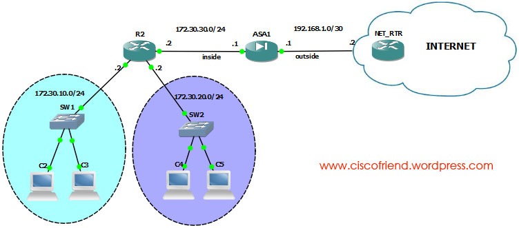
ASA STATIC DEFAULT ROUTING
Syntax of static route configuration is :
Route <interface-name> <ip address> <netmask> <gateway ip> [distance]
Objects:
  • Configure static routing to inside interface
ASA1(config)#route inside 172.30.10.0 255.255.255.0 172.30.30.2 1
ASA1(config)#route inside 172.30.20.0 255.255.255.0 172.30.30.2 1
  • Configure default route to internet
ASA1(config)#route outside 0.0.0.0 0.0.0.0 192.168.1.2
Note: we can use the command “route outside 0 0 192.168.1.2” for default route, both are same.

Friday, November 4, 2011

Installing GNS3 on CentOS 6.x/RHEL 6.x/Fedora 15


  1. Login as root then do the following steps:
    yum install python python-devel xorg-x11-proto-devel libXext-devel gcc-c++ libXrender*

  2. Download and install Qt
    #wget http://get.qt.nokia.com/qt/source/qt-everywhere-opensource-src-4.7.4.tar.gz
    #tar -xzf qt-everywhere-opensource-src-4.7.4.tar.gz
    #cd qt-everywhere-opensource-src-4.7.4
    #./configure -nomake examples -nomake demos -qt-gif -no-exceptions -debug -qt3support
    #gmake
    #gmake install
    #PATH=/usr/local/Trolltech/Qt-4.7.4/bin:$PATH
    #export PATH

  3. Download and install sip
    #wget http://www.riverbankcomputing.co.uk/static/Downloads/sip4/sip-4.13.tar.gz
    #tar -xvf sip-4.13.tar.gz
    #cd sip-4.13.tar
    #python configure.py
    #make
    #make install

  4. Download and install PyQt
    #wget http://ftp.pardus.org.tr/pub/source/2009/PyQt-x11-gpl-4.8.4.tar.gz
    #tar xvf PyQt-x11-gpl-4.8.4.tar.gz
    #cd PyQt-x11-gpl-4.8.4
    #python configure.py -q /usr/local/Trolltech/Qt-4.7.4/bin/qmake
    #make
    #make install

  5. Download GNS3
    #wget http://downloads.sourceforge.net/project/gns-3/GNS3/0.7.4/GNS3-0.7.4-src.tar.gz
    #tar -xvf GNS3*.tar.gz && rm GNS3*.tar.gz
    #cd GNS3-0.7.4-src
    #mkdir Dynamips IOS Project Cache Temp

  6. Download Dynamips depending up on OS (64-bit/32-bit)
    #cd dynamips
    #wget http://downloads.sourceforge.net/gns-3/dynamips-0.2.8-RC2-amd64.bin?download (for 64-bit OS)
    #wget http://downloads.sourceforge.net/gns-3/dynamips-0.2.8-RC3-community-x86.bin?download (for 32-bit OS)
    #chmod +x dynamips-0.2.8-RC2-amd64.bin (if we use 32-bit version, use the name of that file)

  7. Creating Quick launch with gns3 icon
    #wget http://www.noahbeach.com/wp-content/uploads/2011/08/gns3.png
    Now right click on the panel and select add to panel > custom launcher > select the gns3 location and press on the icon button to locate the icon just downloaded. ok
    Now if we press that icon in the panel, gns3 will run...!!!

Monday, October 24, 2011

Configuring router for SDM

Cisco SDM
SDM configuration steps:
  1. Create user accounts
  2. Enable http and/or https server
  3. Configure http to use local user database
R1(config)#username binoy privilege 15 secret cisco sdm launcher
R1(config)#ip http server
R1(config)#ip http secure-server (allows encrypted access)
R1(config)#ip http authentication local
Now download SDM from www.cisco.com/go/sdm and install it in the computer (requires java runtime environment) and launch the SDM by giving IP address in SDM launcher

Wednesday, October 19, 2011

Cisco router password recovery process

  1. Connect to console port
  2. Use the power switch to power cycle the router.Password Recovery
  3. Issue the break sequence within 60 seconds of power up to put the router into ROMmon.
  4. Type “confreg 0x2142” at the rommon 1> prompt.  (This changes the default configuration register and causes the router to bypass the startup configuration where the forgotten enable password is stored.The configuration register is usually set to 0x2102 or 0x102)
  5. Type no after each setup question, or press Ctrl-C to skip the initial setup procedure.
  6. Router> enable
  7. Router#copy start run
  8. Now, change the passwords and give no shutdown commands to interfaces
  9. R1(config)# config-register 0x2102 (To make the startup configuration effective while next booting)

Sunday, October 9, 2011

Administrative Distance of Routing protocols

Connected interface     0
Static route 1
Enhanced Interior Gateway Routing Protocol (EIGRP) summary route 5
External Border Gateway Protocol (BGP) 20
Internal EIGRP 90
IGRP 100
OSPF 110
Intermediate System-to-Intermediate System (IS-IS) 115
Routing Information Protocol (RIP) 120
Exterior Gateway Protocol (EGP) 140
On Demand Routing (ODR) 160
External EIGRP 170
Internal BGP 200
unknown 255

Wednesday, September 28, 2011

Installing and configuring SecureCRT for gns3

Secure CRT Installation

  1. Download secureCRT with crack from internet (There are plenty of places, use google to search “SecureCRT with crack downlaod”)
  2. Install secureCRT
  3. copy the crack to installation directory (eg: C:\Program Files\VanDyke Software\SecureCRT\)
  4. Run the crack as administrator (Right click the crack and in the menu select run as administrator)SecureCRT LOGO
  5. Enter anything in name and company field and press generate. Now, the serials and other information appears.
  6. Press the patch button to patch the secureCRT.exe file. That’s it.  Now the secure CRT installed correctly.

GNS3 configuration of secure CRT

  1. Download and install GNS3, add IOS etc.
  2. Go to Edit > Preferences > General > Terminal settings tab > SecureCRT > Change preconfigured terminal commands to SecureCRT (64 bit or 32 bit depending upon the version installed) > Press “use” button > press okimages
  3. Now add some routers (with IOS added) to work space and turn it on.
  4. Press the console button to see the tabbed windows for each router
Note: if any error occurs, check the installation path of SecureCRT in the terminal command

Thursday, July 22, 2010

How to recover IOS from ROMMON

rommon 1 > IP_ADDRESS=172.30.10.20 (gives IP address to current device)

rommon 2 > IP_SUBNET_MASK=255.255.255.0

rommon 3 > DEFAULT_GATEWAY=172.30.10.1

rommon 4 > TFTP_SERVER=172.30.10.100

rommon 5 > TFTP_FILE=c3640-jk9o3s-mz.123-14.T7.bin

rommon 6 > tftpdnld  (this command will start the download of IOS from TFTP server)

Monday, May 3, 2010

ASA trunk interface configuration

trunkconfiguration
Switch side
Switch(config)#int fa0/9
Swtich(config-if)#switchport
Swtich(config-if)#switchport trunk encapsulation dot1q
Swtich(config-if)#switch trunk allowed vlan 100,101 (if not specified, every vlan  will send to ASA)
Swtich(config-if)#swtichport mode trunk (ASA cannot negotiate trunk using dynamic protocol)
Swtich(config-if)#no shut

ASA side
NOTE: Each physical interface of ASA carry one or more sub interfaces, each carries one vlan

ASA(config)# int e0/3
ASA(config-if)# no shut
ASA(config)# int e0/3.1
ASA(config-subif)# vlan 100 ; specifies which vlan carried over this sub interface
ASA(config-subif)# nameif inside
ASA(config-subif)# ip address 10.1.1.1 255.255.255.0
ASA(config)# int e0/3.2
ASA(config-subif)# vlan 101
ASA(config-subif)# nameif building1
ASA(config-subif)# security-level 50
ASA(config-subif)# ip address 10.2.1.1 255.255.255.0
ASA(config-subif)# no shut

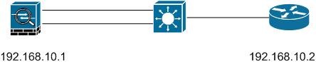
Trunk interface on firewall module
cat6500#show vlan : to see vlan inside switch
cat6500#show module : to see connected module number
cat6500#config t
cat6500(config)#firewall vlan-group 1 10,100 ;says which vlan should send to firewall module, vlan group number can be anything.
cat6500(config)#firewall module 3 vlan-group 1 ; to which firewall module to send these to

Cat6500#session slot 3 processor 1
FWSM> enable
FWSM# config term
FWSM(config)#interface vlan 10
FWSM(config-if)#nameif outside
FWSM(config-if)# ip address 192.168.10.1 255.255.255.0
FWSM(config-if)#no shut
FWSM(config-if)#exit

FWSM(config)# int valn 100
FWSM(config-if)#namif inside
FWSM(config-if)#ip address 172.30.10.1 255.255.255.0
FWSM(config-if)#no shut
FWSM#show int

ASA Redundant Interface


REDUNDANT INTERFACE ASA
ciscoasa(config)# int redundant 1
ciscoasa(config-if)# member-interface ethernet 0/0
ciscoasa(config-if)# member-interface ethernet 0/1
ciscoasa(config-if)# nameif outside
ciscoasa(config-if)# ip address 10.10.10.1 255.255.255.0
ciscoasa# show interface redundant 1 : to check both are operational
at the bottom we can see redundancy information
show interface :- we can see which one is active
show interface | include (Interface|member)
NOTE: if primary interface came up it will not switch back until the current one fails